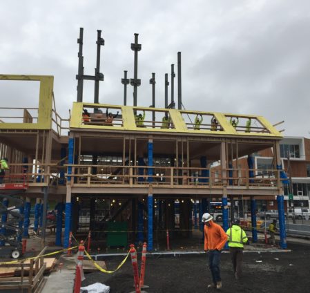
As the winter of 2016 approached, all eyes were on Carbon12. The foundations had been poured and a steel frame stood two stories high, waiting for the wood panels that would enable it to climb skyward. The goal was to build the entire eight story structure in just ten weeks. Here is how it happened.
It was essential that the steel and concrete were ready to accept the CLT panels that were ready and waiting in Canada. The wood package required a tolerance of ⅛”, yet acceptable tolerances for concrete are ½” to 1” depending on location, and up to ¾” for structural steel. It was imperative that the trades worked together to achieve a tight tolerance across the board. The first floor wood columns were sized to assume for some shimming to occur at their base. This allowed the framers to make up for some of the tolerances in the steel bases across the ground floor before the CLT arrived.
The wood columns and beams were installed on the east side first. Once the columns and beams were plumbed, squared and leveled, they were screwed together with long diagonal screws on the top. The framers then moved to the other side and installed the columns and beams. The CLT panels took roughly two days to install, including installation of the splines, steel straps and screws. The first level took roughly two weeks, but the upper floors were completed with a floor every four days.
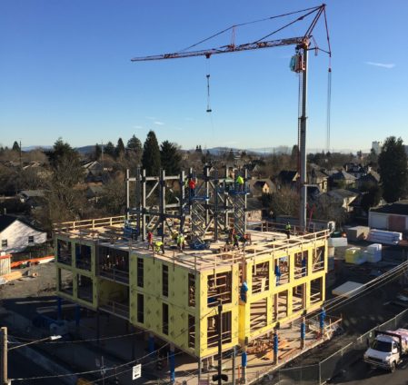
After three floors of CLT were installed, the framers had to stop CLT installation to add the next level of the steel core. They then dropped back and installed the interior walls and stairs to keep the project moving forward and make the floors safe for other trades.
-
How did you achieve tolerance at the ground level between the concrete and the wood?
Frequently Asked Question
How did you achieve tolerance at the ground level between the concrete and the wood?
The wood never directly touches the concrete, the connection is made by custom made steel column bases that were fabricated locally and installed before the wood arrived. The ground level of Carbon12 is a composite concrete and metal deck with exterior concrete curbs.

The concrete subcontractor drilled and epoxied the steel anchor bolts rather than casting them in place to ensure that the column bases were in the exact location. For vertical flexibility, the anchor bolts were left long to allow the steel bases to be shimmed. A half inch of shimming was assumed. If the concrete was higher than assumed, the wood columns would have been trimmed on the bottom. However, this was not needed. After the columns were loaded, the shimmed bases were grouted underneath for additional support. -
How did you provide tolerance between the steel brace frame core and the wood beams that connected to it?
Frequently Asked Question
How did you provide tolerance between the steel brace frame core and the wood beams that connected to it?
In the locations where wooden beams were connected to steel columns, traditional steel buckets were used. The buckets provided adjustability, and beams were trimmed to fit, if necessary. The wood beam to steel bucket connections were drilled and bolted in the field and hidden from view in soffits or embedded in drywall for fireproofing.

 The steel buckets allowed for beams to be shimmed laterally and vertically as needed to keep the wood beams plumb and level.
 -
How did the wood-to-wood fabrication provide tolerance?
Frequently Asked Question
What kind of tolerance did you have in the wood to wood connections?
Since most of the wood-to-wood connectors were factory installed, there were no issues with the connections and no modifications were needed in the field.
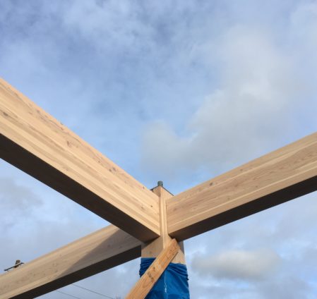 The hidden Ricon connectors highlight the glulam columns and beams, and the invisible hardware give the appearance that they are floating. This harkens back to a traditional way of building with mortise and tenon.
 -
How did you install the exterior wood-framed walls?
Frequently Asked Question
How did you install the exterior wood framed walls?
Initially, the thought was to build the exterior walls with the interior walls during the breaks in the mass timber install while the steel core was erected. However, given that the glulam columns and beams lined the exterior of the floorplate it made it impossible to tilt the walls into place. By the third floor, the sequence was changed so the exterior walls were installed first prior to the placing of the columns and beams.
 The exterior walls on the lower levels were framed and sheathed using ladders and scissor lifts. On the upper floors, the walls were framed and sheathed on the CLT decks and then tilted into place.
 -
Why didn’t you use a concrete core?
Frequently Asked Question
Why didn’t you use a concrete core?
While it seems financially advantageous to use a concrete core, there were more reasons not to. From a cost perspective, subs were already on site pouring foundations. However, due to the tight footprint of the building, crew sizes, and overhead work it would have required the entire core to be poured prior to the start of wood framing. This would have added 6-8 weeks to the overall project schedule (or potentially longer, as the bad weather in December would have delayed concrete pours).
A concrete core would have meant providing block outs and sleeves to route MEPF systems through the walls. The steel core provide ample room to route MEPF, and allow for flexibility during installation of those systems
 Using the steel brace frame with bolted connections allowed the wood framing and steel frame to be erected simultaneously soas to not slow down construction.
 -
How did you use technology to ensure that everything went together as designed?
Frequently Asked Question
How did you use technology to ensure that everything went together as designed?
While the framing subcontractor used traditional levels and lasers, Kaiser+Path used an on-site Total Station. The Total Station not only ensured the project was plumb and level; but also coordinated with the BIM model. At several points it was double checked by a surveying company, Centerline Concepts.


- Learn more about wood supplier, Structurlam
- Read the 2017 Structurlam Carbon12 Case Study
- Learn more about wood and steel installers, Timberland
- Learn more about concrete tolerances in section 4 of the ACI 117-10
- Learn more about steel tolerances, in section 7.13 of the ASIC 303-16
In my 30 years of building, I have not seen a building framed as quickly and efficiently as Carbon 12. The structural steel core and mass timber elements fit together seamlessly - with very little corrective work.
— Scott Noble, Senior Project Manager, Kaiser+Path
On January 27, 2017 the seventh floor deck was installed, making Carbon12 the tallest CLT structure in the United States.
Did You Know?
The entire wood package arrived as a kit of parts. The building had 234 columns and 336 beams, of which only 4 beams had to be trimmed to fit.
Smaller Crews, More Safety
Due to a chronic labor shortage, finding subcontractors and the crews to work on the project was very challenging. Because of the nature of CLT construction, only four carpenters would be needed to assemble Carbon12’s mass timber components.
Smaller crew sizes mean less cost, improved safety, better coordination and added accountability. To prevent damage and staining, the CLT pieces were lifted directly from the semi-truck trailer with no double handling. The pieces were lifted, or “flown”, with the crane to a crew of three carpenters who maneuvered the pieces into place and secured them.
-
How was the steel installed?
Frequently Asked Question
How was the steel installed?
Timberland was both the wood and steel framing subcontractor. While the steel columns and beams were fabricated locally at Timberland’s shop, Buckling Restrained Brace (BRB) Frame cross members were designed and fabricated by Core Brace in Utah and shipped to the job site. To speed up construction, the columns were fabricated in three story sections. The beams and cross braces were all bolted to lessen the risk of welding near the wood and to speed up the install. The column-to-column sections were welded for strength and flexibility. This meant that twice over the course of the framing, the mass timber install had to pause to allow the next section of steel to be erected and welded. During this time, interior and exterior framing proceeded.
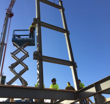 Starting in the basement, the first section rose up to the second floor. Once the second floor wood deck was completed, another steel section was installed using the crane and scissor lifts. This was repeated on the fifth floor as well.
 -
Why didn’t you panelize the interior and exterior walls to double the efficiency?
Frequently Asked Question
Why didn’t you panelize the interior and exterior walls to double the efficiency?
Panelizing interior and exterior walls is a great time and space saver on many job sites. For Carbon12 the concern was that many of the interior walls wrapped around or were infilled around the steel brace frame. Due to the custom nature of the brace frame, these walls could not be predesigned until the frame was bolted and welded into place. The other concern was crane time. Panelized walls require a crane to pick them and lift them into place. Given that the mass timber and steel both required the use of a crane, and there was room for only one tower crane, there was no available time for this. To have utilized panelized walls, even on the exterior, would have extended the schedule or added a mobile crane on site, both of which would have been cost prohibitive.
-
How long would it have taken if you constructed the building using post-tension concrete slabs?
Frequently Asked Question
How long would it have taken if you constructed the building using post-tension concrete slabs?
Replacing Carbon12’s structural elements (steel core and BRB brace frame, glulam beams and columns plus CLT floor and roof plates) with post tensioned concrete slabs and regular concrete columns would have added an additional 10 weeks to the construction schedule.
All of the concrete elements are formed on site with little prefabrication, placing reinforcing steel and tendons, cure time, concrete pumping and placement, waiting for the concrete to reach minimum tensioning strength, tensioning, removing formwork and re-shoring until the concrete reaches design strength, removing the reshores after design strength is achieved and loading from floors above is reduced, then the process is repeated for the next floor. Once a floor is clear of re-shores, only then the MEPF rough-in can begin. For Carbon12, this process would have taken on average 2 ½ weeks per floor.
The steps required for concrete construction are unnecessary with mass timber. Once wood columns and beams are placed, and the CLT panels secured, MEP rough-in can start immediately. This process took on average 5 days per floor for Carbon12.
-
What kind of equipment did you use to install mass timber and steel components?
Frequently Asked Question
What kind of equipment did you use on Carbon12 to install mass timber and steel components?
A Potain HDT 80 was used for Carbon12 which is a self-erecting tower crane that avoided many of the costs and logistics around a larger tower crane set up. This smaller crane type was capable of meeting the needs of the job due to the relatively small footprint of building and the ability to place the crane close to the structure with easy access to pick up loads. With the crane doing most of the heavy lifting, the subcontractors were able to employ standard scissor lifts to work on the steel, and fork-lifts to move materials, and booms to install exterior siding. After the crane was taken down, a Safway Personnel Hoist was installed to move materials and workers to the upper levels of the building.

The Wood Mock Up
Before the mass timber was fabricated, Kaiser+Path designed a mini-Carbon12 cross-section to ensure the look, constructability and mobility of each piece was taken into account. When the mock-up arrived at the construction site, it was installed and evaluated. Tweaks and modifications were quickly made, comments were compiled and sent back to the manufacturer. Examples included: adding a pick point to the top of the columns so they could easily be craned into place, and identifying areas that needed more or less tolerance to ensure a tight fit. These adjustments proved invaluable not just for speed but also for safety.
Cold Temps And Snowy Weather
Framing took place between December 2016 and February 2017, which was one of the wettest, coldest, snowiest winters in recent history. While most of the construction sites in town were closed for several days at a time, Carbon12 continued to rise.

Snow Inside The Building — Crews arrived on site and spent the first few hours clearing snow so that work could continue.

Snowy Roads — Mass timber can be installed in any temperature and weather condition. It is not limited by cure temperatures or welding torches.
Avoiding Waste
Mass timber members were cut, modified and finished before they reached Carbon12’s site. By taking the cutting, connector install and notching out of the field and putting it into the factory, waste and on-site mistakes were eliminated. The mass timber components went through a rigorous quality control process in the production facility. This saved time on site and avoided the need to order extra attic stock in case of miscuts. Structurlam requires that the wood waste from their factory be used as biofuel, giving it a second life as a power producer.
During framing, only two dumpsters were used. These contained scraps from the interior framing and the protective wrap that covered the CLT panels during transportation. Oregon requires construction dumpsters go to recycling centers to be sorted. However, the materials are co-mingled and there is a large amount of recyclable or reusable material that ends up being damaged or wasted. By lessening the use of dumpsters, money was saved and the likelihood of materials being recycled properly was greatly increased.
Did You Know?
All the mass timber for Carbon12 was trucked from a facility in British Columbia to the jobsite by one driver making multiple day-long trips; swapping out the loaded trailer with an empty trailer for the return trip.

The truck driver left the CLT production facility in Penticton, BC in the early evening. Driving all night, he arrived in Portland around dawn. He slept for a few hours in his truck before arriving at the job site at 6:00am. He dropped his fully loaded trailer, grabbed some breakfast and hitched up the empty one from the previous trip to head back to Penticton.
Acoustic Floor System
Since the acoustic system was a custom design of disparate parts, Kaiser+Path hired multiple subcontractors: one to install the initial insulation and base layers, another to install the gypcrete topping slab and finally one more to install the finished floor products. Securing the initial materials, particularly the insulation board, proved challenging because the size of the material was a special order. Roughly 2,200 sheets of insulation board took 12 weeks to arrive in Portland.
The flooring process began by closing up any gaps in the sub-floor system. Many locations where the CLT was notched around steel columns and beams to allow for installation had to be blocked with expandable foam, sheet metal closure strips and wood blocking. The bottom of the walls received a layer of ⅜” isolation foam to acoustically separate the floor system from the walls. For extra moisture protection, a layer of plastic sheathing was added to the bare CLT, then wrapped up the columns and walls and then seams were taped. The entire floor was closed to all trades except the electricians who needed access to run power through the built up floor system to exterior walls and ceiling boxes. With the electrical work completed and inspected, the first layer of insulation board was installed on the entire floor - omitting areas where electrical raceways were located.
Next, rigid DensDeck board was installed over the insulation board. Then another layer of insulation board was installed, taking care to stagger the joints to avoid gaps through the “sandwich” of insulation.The process took a week per floor to prepare for installation of the gypcrete.
The 1.5” gypcrete topping slab install took three days. The first day consisted of installing a slip sheet on top of the insulation board, and then wire mesh. The second day was pumping and placement of the gypcrete. For efficiency in placement, the gypcrete was placed on two floors at a time. The third day allowed the gypcrete topping slab to cure and set enough to be walked on the following day.
The entire process meant that for almost two weeks two floors were “offline” to all subcontractors and crews except for those specifically working on the flooring system. Because of this, the MEPF rough-in was completed in the space prior to the flooring system and as soon as the gypcrete floors were poured, installation of the drywall could take place. The last layer of the floor system was an acoustic mat that was placed under the hardwood floor through a combination of floating and glue down. The mat provided the benefit of separating the wood from the gypcrete, allowing it to expand and contract and not transferring footfalls directly to the gypcrete. The robustness of the entire floor assembly plus the fact that there are no shared walls between units provides a similar acoustic experience as living in a detached single family home.
-
Learn more about the Sika AcouBond-System
Sika AcouBond-System
AAcoustics specified the Sika Acou-Bond System as the underlayment for the engineered wood floors. The material is European and is not common in the US. It was difficult to find a flooring installer that had ever used the system and many were reluctant to install it or warranty it. In the end, the flooring went in easily and the system worked well.
- Learn more about the flooring installers, Paulson’s Flooring Coverings
- Learn more about the drywall team, Plumbline Drywall
- Learn more about the gypcrete crew, Acousti-Level
Rain, Rain, Rain
Starting in mid-February, it rained almost constantly for the next six weeks, preventing the roof system from being installed.

Tent — The building was capped with a large tent in late March and into April to keep the rain off the CLT roof deck. Fans circulated warmed air to bring the moisture in the CLT down to acceptable levels so the roof could be installed.

Roofing — Roofers used a breathable SBS sheet directly on top of the CLT that tied into permanent roof vents. A TPO roof was installed on top of the tapered insulation to provide a weather tight and energy efficient system.
Careful Coordination
Like CLT itself, the Mechanical, Electrical, Plumbing and Fire systems (MEPF) requires careful up-front coordination. Carbon12 was built using a design-build approach with the subcontractors. During the longer-than-usual permitting process, time was dedicated to MEPF pre-design to ensure that the shaft pre-cut in the CLT manufacturing facility would accommodate all of the building systems. Hours of meetings were held on each shaft, soffit, and ceiling in an effort to reduce the size of ducts and pipes, ensure structural integrity, and to create a sequencing plan to allow subcontractors to install their systems without impeding others' work.
The meetings and subsequent installation were challenging as each contractor negotiated for the space and location that would be most advantageous for their tasks. The dedicated MEPF teams created workarounds and custom solutions to adapt to the spaces provided. At times this meant less efficiency, either with materials or install time. It helped that the floors were identical so improvements were made as they progressed. In the end, the subcontractors were working together like a well-oiled machine.
- Learn more about the HVAC team, Portland Mechanical Contractors
- Learn more about the electrical, fire alarm, and security team, Stoner Electric Group
- Learn more about the plumbing team, D&F Plumbing
- Learn more about the fire sprinkler team, Patriot Fire Protection Inc
Leaving as much exposed wood as possible proved to be a true challenge. To do it, we had to coordinate all the trades into a few small soffits and drop ceilings. Each unit is 1500 square feet but all four trades were vying for space in one 200 square foot soffit.
— Taylor Cabot, Project Manager, Kaiser+Path
More On Construction
HVAC
An energy efficient, all-electric LG VRF system.
Read moreHVAC
Carbon12 uses an electric LG VRF (Variable Refrigerant Flow) system. These are often used in commercial applications where there are many zones that can benefit from being interconnected and share the loading. This makes the system very efficient. Each of the condo units have their own fan coil unit controlled by its own thermostat. Each floor shares an ERV (Exhaust Recovery Ventilator) which is a heat exchanger which transfers the heat of exhaust air to the incoming fresh air. This warms the fresh air to reduce load on the system. Each floor also uses a branch box to allow refrigerant to be shared from the east side unit to the west side unit. This balances the system and ensures the refrigerant is used to its maximum capacity. All the fan coil units share condensers. There are two on the roof for the 7th and 8th floor and four on the ground level for floors 1-6.
The two ground floor retail units have their own HVAC systems and the basement uses exhaust air from the electrical equipment (heat) as well as room specific electric heaters for freeze protection. Each condo unit has its own fresh air intake on its balcony. Each unit has a point of source exhaust fan in the bathrooms and in the kitchen, but also has a 24/7 fan on the roof to maintain positive pressure to exhaust odors and steam. The dryers also have a 24/7 exhaust fan that exhausts on the rooftop.
Several alternative HVAC systems were explored including in-floor radiant heating (which was ruled out due to concerns about having water buried in the floor and the potential for leaks. Smaller mini-split systems were also considered which would give each unit its own fan coil unit and condenser unit rather than sharing condensers. While this is simpler for the user, it loses the energy efficiency of a larger system that shares and offsets the loads. It would have also required 14 condensers to be placed on either the roof or on the ground level. Space was limited and there was no place to “hide” them from view (as required by design review and out of interest for the condo owners).
LG VRC System Specifications
Electrical
An energy efficient and technologically advanced electrical system.
Read moreElectrical
Special care was taken to make Carbon12 an electrically efficient building. In each unit, there are state of the art electrical appliances including induction cook-tops and convection ovens. All of the units use dimmable LED lights. The main living areas have Leviton bluetooth switches to allow for remote control of lighting from a phone or portable device.
Lighting was kept simple and clean in the soffits and drop ceilings. 2700 degree warm fixtures were specified throughout to cast a warm, residential feel. Concealed electrical power was run to ceiling boxes or lighting tracks to allow for flexible lighting options while still avoiding exposed conduit or wires on the ceilings.
In the common areas including the stairwells, basement hallways and storage rooms, occupancy sensors were installed to ensure that lights are never left on. The exterior lighting on the project is also LED and operated via photocells.
The building includes infrastructure for a solar array on the roof. With the conduit and stanchions for installing the array in place, the HOA can decide at anytime to add panels and collect the electricity for use in the building. The array was not installed during construction as the credits and incentives are rolled out over several years and should benefit the building and owners- not a single entity.
Plumbing
An efficient and shared hot water plumbing system.
Read morePlumbing
Carbon12 employs a shared hot water system with instant hot water available throughout the building. The backbone is a lead-lag system of gas powered hot water heaters (the only gas powered equipment in the building). These heaters are located in the basement and work with a system of booster and re-circulation pumps to deliver on-demand hot water. All the sewer lines are cast iron to reduce sound. Cast iron and its rubber gasket transitions are known to reduce sound transition by 750%. They are inherently fireproof and more recyclable than PVC.
The main water lines in the building are copper. Copper piping while more expensive and labor intensive is known to have less failures due to poor connections, it’s also less susceptible to fire and is extremely recyclable. After the water lines reach the units they transition to PEX to allow for greater flexibility through framed walls and tight soffits and to allow for easy future modification as needed.
All of the rainwater from the roof is captured and discharged to an underground storm water gallery system - where it slowly filters back into the ground - bypassing the city sewer system. The paving system around the building is permeable, allowing water to soak into the ground
Sprinkler
A fire sprinkler design with superior coverage and minimal visual impact.
Read moreSprinkler
As part of the fire prevention requirements, Carbon12 had to be fully sprinklered. The building has a separate 6” water line specifically for the fire protection system. Given the available water pressure from the city and relatively low amount of sprinkler heads in the project, an on site fire pump was not required.
The water line enters the building in the basement and then uses the stairwells as a logical pathway for the standpipes and drains. Enlarged intermediary landings have isolation valves for each floor. Once inside the units, the sprinkler lines are hidden in dropped ceilings in the elevator entries, hallways, and bathrooms. The sprinkler heads in the ceilings and soffits have concealed heads, which appear as small white disks on the soffit walls and drywall ceilings.
There are only two locations where the sprinkler line is visible: a small section in the master bedroom leading to the closet and two bays of the living room by the balcony. In all instances the sprinkler lines were painted white to blend in with the walls.
Exterior Finishes
High quality fiberglass windows and durable custom metal and wood siding.
Read moreExterior Finishes
To maintain as much window area as possible, Cascadia Fiberglass Windows were used. They have insulated fiberglass frames to reduce thermal bridging. The excellent r-value meant that there was more window area without negatively affecting the thermal performance of the building. The initial designs called for wood on the exterior of the building to signal the structural material inside. However, wood is not an approved building material above four floors on the exterior according to fire code. Extensive research was done to find a material that could resemble wood siding. Most materials that look like wood are made for single family residences which do not have strict enough fire-resistance or wind force requirements.
A painted metal panel that abstractly resembles birch bark was chosen for the primary facade material. The siding installer, Architectural Metal Works, customized the panel with a varied pattern inspired by nature. The secondary material is a real wood veneered panel that meets the required fire ratings. At the ground floor, where wood was allowed, glulam fins with stainless steel brackets were installed to provide a more authentic and tactile experience at the pedestrian level.